|
RESIDENTIAL / LIGHT COMMERCIAL
COMBUSTION AIR IN-FORCER™ |
THE
PROBLEM:
Incomplete
combustion or poor draft due to inadequate combustion air in too-tightly
constructed buildings can result in carbon monoxide creation, poor equipment
efficiency, reduced equipment life and nuisance service calls.
|
|
THE
SOLUTION:
The
IN-FORCER mechanically draws outside air indoors on demand to provide fresh
air for safe and efficient operation of fuel burning equipment. |
The Combustion Air IN-FORCERTM
offers all these advantages:

|
Affordably priced and installs
fast with simple electrical interlock. |

|
Reduces cold air drafts through windows, doors,
fireplaces caused
by excessive negative pressure. |

|
Automatic regulated control of
incoming fresh, combustion air. |

|
Light indicates
IN-FORCER is operating properly. |

|
Uses indoor air to temper outdoor
air for increased comfort. |

|
Interlock shuts down
burner if intake elbow is blocked or performance
is significantly reduced. |

|
Damper closes during off cycles to prohibit cold
air entry and warm air
loss. |

|
Helps replace air
vented by exhaust fans, fireplaces, etc. |

|
Reduces negative pressure, a major cause of flue
gas spillage and radon
gas entry. |
|
|
Steps
to Selecting the Right Combustion Air IN-FORCERTM
MODEL PAI-2G
MODEL PAI-2O
(For 24 VAC Control Circuits) (For 115 VAC Control Circuits)
|
Step 1) |
Determine the required CFM from Table A
based on equipment type and BTU/hr. input of the heater(s).
|
| Step 2) |
Calculate
the equivalent length of the 3" PVC inlet pipe and the
6"outlet duct (if used) from Table
B.
|
| Step 3) |
Referencing Table
C and your calculated equivalent length, verify that the CFM performance
listed in Table C is equal to or greater than that
determined in Table A. Select Model PAI-2G or PAI-2O
Series
based on control circuit voltage.
|
REQUIRED CFM BASED ON EQUIPMENT TYPE
AND BTU/HR INPUT (TABLE A)
|
BTU/HR INPUT
|
GAS ATMOSPHERIC
|
GAS INDUCED
COMBUSTION
|
OIL FLAME RETENTION
|
|
40,000
|
21
|
11
|
12
|
|
50,000
|
26
|
14
|
15
|
|
60,000
|
32
|
17
|
18
|
|
70,000
|
37
|
19
|
21
|
|
80,000
|
42
|
22
|
24
|
|
90,000
|
47
|
25
|
27
|
|
100,000
|
53
|
28
|
30
|
|
110,000
|
58
|
30
|
33
|
|
120,000
|
63
|
33
|
37
|
|
130,000
|
68
|
36
|
40
|
|
140,000
|
74
|
39
|
43
|
|
150,000
|
79
|
41
|
46
|
|
160,000
|
--
|
44
|
49
|
|
|
BTU/HR INPUT
|
GAS ATMOSPHERIC
|
GAS INDUCED
COMBUSTION
|
OIL FLAME RETENTION
|
|
170,000
|
--
|
47
|
52
|
|
180,000
|
--
|
50
|
55
|
|
190,000
|
--
|
52
|
58
|
|
200,000
|
--
|
55
|
61
|
|
210,000
|
--
|
58
|
64
|
|
220,000
|
--
|
61
|
67
|
|
230,000
|
--
|
63
|
70
|
|
240,000
|
--
|
66
|
73
|
|
250,000
|
--
|
69
|
76
|
|
260,000
|
--
|
72
|
79
|
|
270,000
|
--
|
74
|
--
|
|
280,000
|
--
|
77
|
--
|
|
290,000
|
--
|
80
|
--
|
|
|
|
CALCULATING EQUIVALENT
LENGTH (TABLE B)
The performance shown is
based on equivalent feet. To determine
the
equivalent feet of an installation add the length of the 3" PVC inlet pipe
plus the equivalent length of any elbows. Do not include the intake elbow
or gooseneck equivalent loss, they have already been factored into the
performance data. Use the same method to determine the equivalent feet
if a 6" outlet duct is installed.
EQUIVALENT LENGTH OF ELBOWS
|
ELBOW DIAMETER
|
90 degree elbow
|
45 degree elbow
|
|
3" PVC
|
5'
|
2.5'
|
|
6"
|
10'
|
5'
|
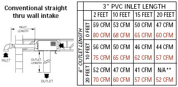
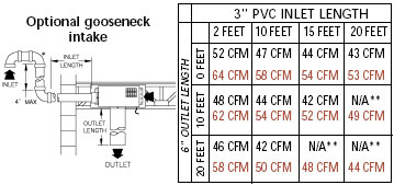
IN-FORCERTM
PERFORMANCE DATA (TABLE C)
| Conventional straight thru wall intake
Models PAI-1G & PAI-1O
(Discontinued)
Models PAI-2G & PAI-2O
** Below Fan Prover Set Point |
 |
| Optional gooseneck intake
Models PAI-1G & PAI-1O
(Discontinued)
Models PAI-2G & PAI-2O
** Below Fan Prover Set Point
|
 |
DIMENSIONS & MOTOR SPECIFICATIONS
|
A
|
B
|
C
|
D
|
E
|
F
|
 |
|
17 3/4"
|
15 5/8"
|
8 7/8"
|
2 5/8"
|
8"
|
9 3/8"
|
MOTOR SPECIFICATIONS
115/1/60 1600 RPM
80 WATTS 1.0 FLA
|

